Sectional Diagram in Architecture (2025 Guide)
When I think of sectional diagrams, I’m reminded of dollhouses that open from the side, revealing all the rooms and their interactions across vertical and horizontal planes. It’s mesmerizing to see how spaces connect and function together, sparking endless imagination as a child about how people might live in those miniature homes.
Similarly, sectional diagrams serve as a powerful tool in architecture, providing clients with a clear and engaging view of their future building’s internal dynamics. They bridge the gap between technical design and human experience, making it easier to visualize spatial relationships and functionality.
In this article, we will first explore what a sectional diagram is and share tips for creating an exceptional one. Then, we’ll delve into the key differences between sectional diagrams and plan drawings, highlighting how each contributes uniquely to the design process.
What is a Sectional Diagram?
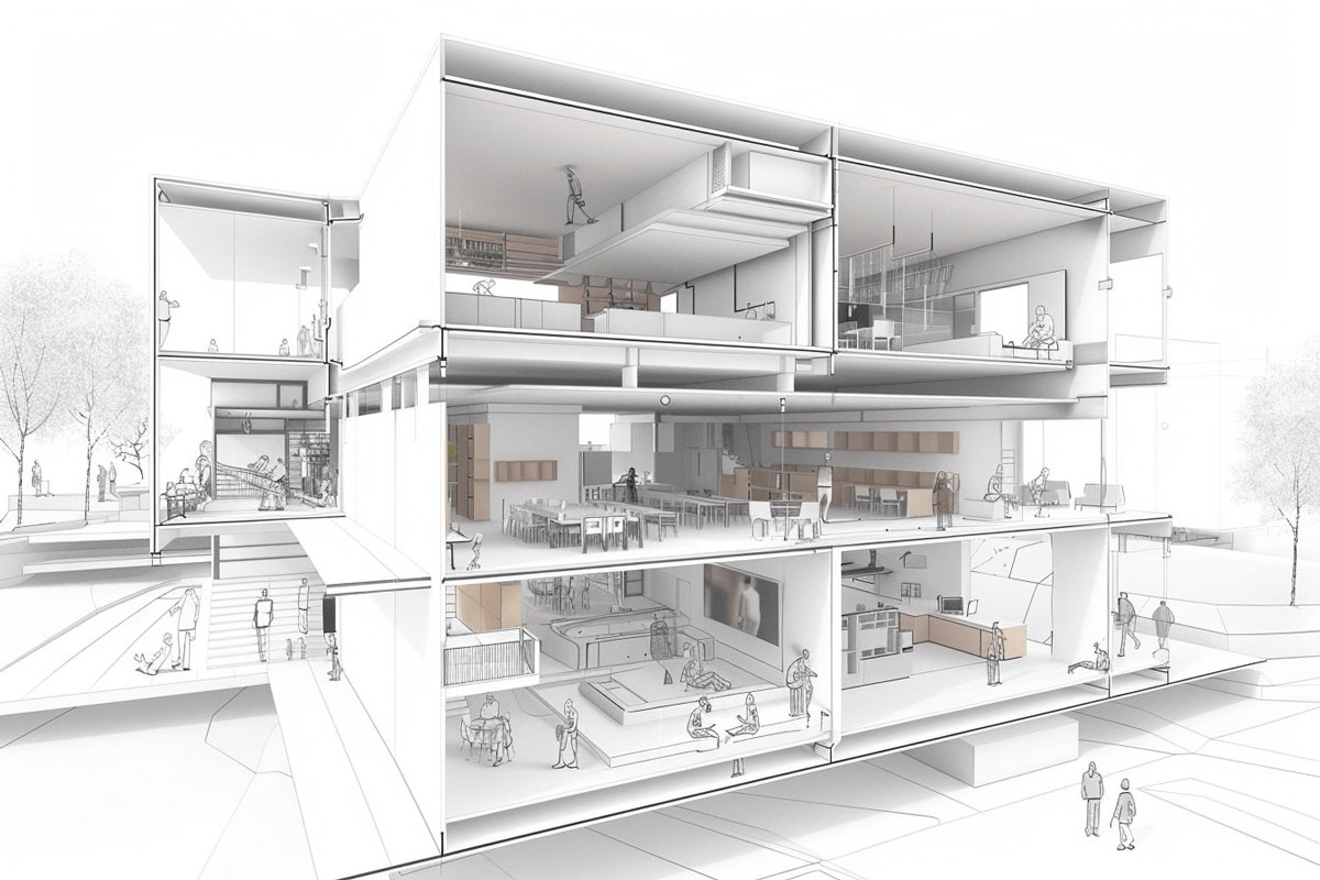
A sectional diagram offers a vertical cross-section of a building, unveiling aspects that flat drawings cannot capture. Much like slicing a cake to reveal its layers, a sectional diagram cuts through a structure to expose its internal spatial relationships, structural components, and the interaction between different levels.
Beyond revealing the building’s interior, this technique also illustrates its connection to the surrounding environment, including the topography and nearby structures. The cut line, typically marked on plan drawings and elevations, serves as a guide, providing viewers with a clear understanding of the building’s three-dimensional form and internal composition.
Tips for Creating an Outstanding Sectional Diagram
Crafting a sectional diagram that communicates effectively requires a balance of technical precision and visual clarity. Here are some essential tips to elevate your sectional diagrams:
1. Define the Purpose
Start by identifying the key message or purpose of the section. Whether it’s showcasing spatial relationships, structural systems, or environmental interactions, knowing your focus will guide the level of detail and features to emphasize.
2. Choose the Right Cut Line
Select a cut line that highlights the most critical aspects of the design. For example, position it through spaces with the most interaction, like staircases, atriums, or areas where levels intersect, to provide the most informative view.
3. Maintain Clarity and Simplicity
Avoid overloading the section with unnecessary details. Focus on elements that directly contribute to understanding the design, and use clean, consistent line weights to distinguish between cut planes, background elements, and annotations.
4. Highlight Key Features
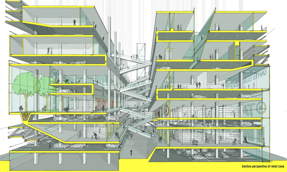
Use shading, textures, or colors to emphasize important elements such as materials, structural components, or circulation paths. This can help draw attention to specific design features without overwhelming the viewer.
5. Incorporate Context
Include relevant environmental or site features, like terrain, neighboring structures, or vegetation, to provide a sense of the building’s relationship with its surroundings.
6. Use Annotations Wisely
Add concise labels or callouts to explain significant features, materials, or systems within the section. These annotations should enhance understanding without cluttering the diagram.
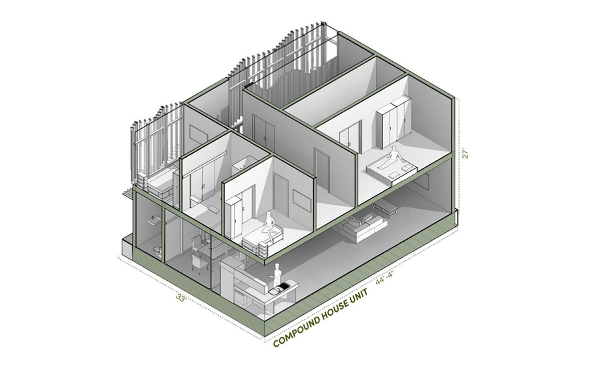
7. Pay Attention to Scale
Ensure the diagram is scaled appropriately to accurately depict proportions and relationships between spaces. Consider including a scale bar or reference objects, such as people or furniture, for context.
8. Leverage Digital Tools
Modern design software can help create precise and visually compelling sectional diagrams. Experiment with rendering techniques, such as transparency or layering, to add depth and clarity.
9. Test Legibility
Step back and evaluate whether the diagram is easy to read and understand. Sharing it with others for feedback can help ensure your message is clearly conveyed.
By following these tips, you can create sectional diagrams that are not only technically accurate but also visually engaging and easy to interpret, effectively communicating your architectural vision.
Sectional Diagrams vs. Plan Drawings
When comparing sectional diagrams to plan drawings, we juxtapose a vertical perspective with a horizontal one, each serving unique purposes in architectural design.
Plan Drawings
Plan drawings offer a bird’s-eye view of a building, showing the layout of spaces from above. They are critical for understanding:
- Spatial Organization: Visualizing room layouts and overall floor arrangements.
- Functional Flow: Analyzing movement patterns, room adjacencies, and accessibility.
- Furniture Placement: Planning interior setups for optimal utility and aesthetics.
Plan drawings are particularly useful for discussions about dimensions, circulation, and the functional zoning of spaces, ensuring clarity in the horizontal configuration of the design.
Sectional Diagrams
In contrast, sectional diagrams provide a vertical cross-section of the building, revealing:
- Vertical Relationships: How different levels of the structure interact, including floor and ceiling heights.
- Structural Elements: The placement of beams, columns, and walls in relation to each other.
- Environmental Dynamics: Integration of natural light, ventilation, and views within the vertical framework.
Sectional diagrams go beyond layout to explore the depth, height, and materiality of spaces, offering insight into how the building functions and feels in three dimensions.
Complementary Perspectives
Both drawings play complementary roles in architectural design. While plan drawings excel in illustrating spatial flow and utility, sectional diagrams add depth by addressing the vertical interplay of elements. Together, they provide:
- Comprehensive Understanding: A full picture of the design’s horizontal and vertical dimensions.
- Enhanced Collaboration: Aiding architects, engineers, and stakeholders in visualizing and refining designs.
- Thorough Documentation: Ensuring every aspect of the project is communicated clearly for construction.
By integrating sectional diagrams, plan drawings, and other visual tools like elevations, architects can transform conceptual designs into fully realized structures, balancing aesthetics, functionality, and structural integrity. Each drawing type contributes uniquely, ensuring no detail of the project is overlooked.
Resources: aaup | illustrach | UNC Learning Center